< Previous | Contents | Next >
SECTION 8.1 OUTPUT CONFIGURATION
![]()
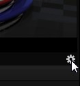
Roll the mouse pointer over the Program monitor to reveal a Configure button (Figure 120) at right in the titlebar below the display. Click it to open the Output Configuration panel. The features offered in this panel vary buy model.
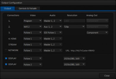
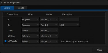
FIGURE 121 (TRICASTER 8000 SHOWN)
FIGURE 122 (TRICASTER 410 SHOWN)
![]()
![]()
The Output Configuration panel contains a pane governing TriCaster’s outputs, and may also include a tabbed pane with Genlock & Failsafe options (Failsafe only for TriCaster 410) and settings. (TriCaster Mini does not have genlock or failsafe options.)
OUTPUTS 1 AND 2
![]()
The first tab, labeled Output, provides control over all of TriCaster’s Output channels. Each of these is in some ways unique. Outputs 1 and 2 are of particular interest, for several reasons:
Of all of TriCaster’s outputs, Outputs 1 and 2 support the most diverse range of optional video sources.
The other outputs can be assigned to ‘follow’ the audio and video source selections of either Output 1 or Output 2, or show certain other sources.
Uniquely, Output 2 can be tasked with sending an alpha channel matte to downstream systems.
Let’s consider the optional settings provided by these two important outputs:
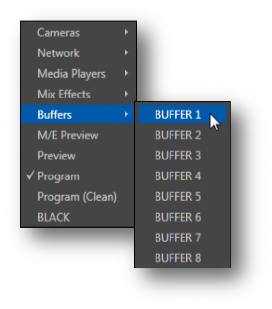
Video menu (Figure 123) – assign any source from the following list to either
Output 1 or Output 2:
o Cameras 1-(4 or 8)
o Network 1 or 2
o Media Players
DDR 1
DDR 2
GFX 1
GFX 2
o Any single Buffer
o Output from M/E 1- (4 or 8)
o M/E Preview
o Preview (look ahead)
o Program
o Program (Clean)
o Black
o Alpha Matte – Output 2 only
Audio menu (Figure 124) – choose which audio is presented on the corresponding Audio Out connector groups on TriCaster’s rear from the following list:
o Outputs
Master 1, 2 (sound from the Master 1 and 2 busses)
Aux (sound from the Aux 1 and 2 busses)
(See Section 15.7.2 for discussion of TriCaster’s internal audio busses).
o Inputs 1-(4 or 8) – sound from any single audio input
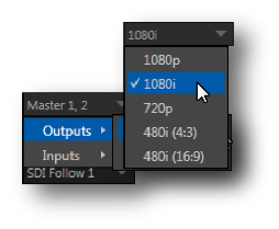
Resolution menu – select the video format for downstream devices you intend to connect to the corresponding output:
o 1080p
o 1080i
o 720p
o 480i (4:3)
o 480i (16:9)
o 576i (4:3) – Multi-format TriCasters only
o 576i (16:9) – Multi-format TriCasters only
Note: Options shown in this menu vary by session format. Also, since Output 1 always transmits video in ‘session format’, an information display is shown rather than a Resolution menu for this output .
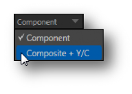
Analog Out menu (not present on TriCaster 410 or TriCaster Mini) – select the video connection type for downstream devices you intend to connect to the corresponding output:
o Component
o Composite + Y/C
FIGURE 125
Note: The only analog connection type suitable for HD video is Component. The Analog Out menu for Outputs 1 and 2 are automatically set to Component and locked when the current Resolution selection for the row is HD.
Choosing Component or Composite + Y/C results in the output connectors in the corresponding row being configured as shown in the following table:
Connection Type | BNC 1 (SDI) | BNC 2 (Y) | BNC 3 (Pb) | BNC 4 (Pr) |
Component | SDI | Y | Pb | Pr |
Composite + Y/C | SDI | Composite | Y | C |
Note: TriCaster’s digital (SDI) video outputs are always active, even when the analog outputs in the same group are in use.
ALPHA MATTE
The Video source menu options for Output 2 include a switch labeled Alpha Matte. This feature can be used independently, or supplement the Act as Alpha option (discussed in Section 8.2.2).
An alpha matte can be automatically derived from suitable sources. It might be the matte from a LiveMatte keyer effect, allowing Output 2 to support downstream compositing of the full color source. Or, it could be drawn directly from an image or Title Page in a Media Player. It could just pass-through the matter from an upstream alpha channel source. Simply enable the switch in the Output Configuration panel, and select a suitable source using the same menu.
Note: Generally, the source’s Resolution should match session format when supplying an Alpha Matte signal to downstream devices.
GENERAL NOTES
Here are some other noteworthy facts related to output:
o For SD session formats, session aspect (4:3 or 16:9) is respected on output (e.g., when the session is SD 16:9, video output is also 16:9).
o For HD sessions (which are always 16:9), SD video from Output 2 (and any output set to Follow 2) can use either a 16:9 image aspect or as (side- cropped) 4:3 video, as noted earlier when discussing the Resolution menu.
OUTPUT 3, 4 (HDMI), STREAM AND NETWORK
![]()
These outputs (provided on a certain models) independently offer a subset of the options available for Outputs 1 and 2. Video menu options include:
Cameras 1-(4 or 8)
Network input sources
Media Players
Buffers
Follow 1
Follow 2
Choosing either Follow 1 or Follow 2 transmits the same video source, at the same resolution, as the ‘followed’ output. For SDI output only, audio from output 3 can follow Output 1 or Output 2.
Note: The Analog Output menu for Output 3 always shows both Component and Composite + Y/C options. (As you would expect, the latter options do not support HD sources, and will fail if selected in that case.)
For 8-input TriCasters, Output 4 is labeled HDMI in the Output Configuration panel as well as on TriCaster’s rear connection panel. Otherwise it is simply labeled HDMI. HDMI menu options are similar to those listed above; HDMI, naturally, does not require analog connection options.
Note: HDMI display devices will typically show black when if they do not support video displays of the format (resolution, etc.) selected as source in Output 4’s Video menu.
Generally, source formats that are inconsistent with the current output resolution setting are automatically conformed when possible. In some cases, such as non-standard image or iVGA sources, the output format may be modified to provide a suitable display. It’s best to avoid non-standard sources whenever possible.
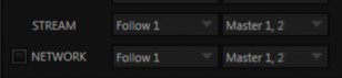
FIGURE 126
Network Output sends audio and video across a LAN (Local Area Network) to the Net inputs of another TriCaster, and is enabled or disabled using the switch at left. A De- Interlace option is provided for Network out. This is useful for connection to downstream systems that re-stream TriCaster’s network video output but lack native ability to de-interlace it (TriCaster’s own streaming output is always de- interlaced).
Streaming Output is more complex, since there are so many different ways to stream. In this panel, you can configure the audio and video sources sent to output. All other options and settings relevant to streaming are located in the Streaming Configuration panel – see Chapter 18 for a full discussion of this important topic.
DISPLAY OUTPUTS
![]()
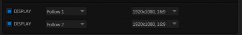
FIGURE 127
Two rows at the bottom of the configuration panel are labeled Display. The corresponding output ports are intended to supply video to projection systems or other display devices.
The physical Display connectors may vary by model, but are typically presented physically on TriCaster’s rear connection panels as HDMI and either DVI or VGA ports. No audio is supplied to these connectors.
When a downstream monitor is detected on a Display port, the corresponding Resolution menu permits selection of a suitable resolution (typically, an incorrect selection here will result in an ‘out of range’ error message being displayed on the downstream device).
Switches provided at left in each row permit the Display ports to be selectively disabled when they are not required.
Note: TriCaster Mini, depending on the model, may also provide CASE DISPLAY setup features, providing access to a number of useful display alternatives for the side-panel LCD screen.
![]()
![]()
TriCaster’s Genlock feature allows it to ‘lock’ its video output to a reference video signal supplied to its Genlock input connector. (Note that neither TriCaster 410 nor TriCaster Mini include Genlock options.)
This synchronizes TriCaster output to other external equipment locked to the same reference. Genlocking is not a requirement, but it is very beneficial, and you should definitely use it if you have the capability.
TriCaster mixes and switches output from up to eight camera sources (8-input models). Miniscule local timing differences between these may force tiny delays during switching operations, which can also contribute to throughput latency.

Hint: The term “genlock” refers to
“generator locking”.
Professional video devices often provide a “genlock input”, which allows an external reference signal (often referred to as ‘house sync’) to control its video timing.
The output of video devices connected in this manner is synchronized to the reference signal, and they are referred to as ‘genlocked’.
Thus, serving i) TriCaster’s Genlock input and ii) other video devices in the chain with a single reference is the best approach.
You could think of it this way:
Genlocking your cameras has the effect of locking their output together, ensuring optimal synchronization for live switching. This may result in throughput latency benefits.
Supplying the same sync source to TriCaster’s Genlock input ensures a match between TriCaster output and any downstream video devices required to handle both it and other (genlocked) sources.
Note: Digital audio is less tolerant in certain respects than analog. Some devices require SDI sources to be genlocked when mixing digital audio (whether for recording or live production).
TriCaster, however, includes dynamic audio re-sampling for each input. Genlocking of SDI audio/video sources is not a requirement. Still, genlocking sources and TriCaster to a house reference signal, or genlocking the cameras directly to the TriCaster output is encouraged (to genlock cameras, see your camera manual).
VERTICAL POSITION, HORIZONTAL POSITION AND PHASE
![]()
Locking all devices to house sync is important, but this alone does not actually ensure a perfect downstream match. Consider an army marching along: each step the soldiers take occurs at precisely the same moment, so we could say their timing is synchronized. Even so – problems result if one soldier leads with the left foot while everyone else is on the right. Or perhaps everyone is evenly spaced and perfectly aligned but for one misfit who ‘tailgates’ the soldier ahead of him and keeps stepping on his heels.
This is essentially why TriCaster provides several adjustments in its Genlock section. The Horizontal and Vertical Position settings pin the image in the proper space in the frame, and in doing so could be likened to making sure each marching soldier is in position relative to his fellows (as viewed from above).
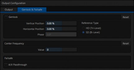
FIGURE 128
The Phase setting ensures proper color alignment, corresponding to making sure everyone is on the left or right foot at the same time.
Thus, the Vert Position, Horiz Position and Phase settings allow you to tweak synchronization to arrive at an optimum match between devices. Typically, these settings are fine-tuned with the aid of a downstream Vectorscope and Waveform Monitor. (A discussion of these adjustments goes beyond the scope of this manual, but a quick online search for the keywords “genlock” and “adjust” turns up a number of excellent references).
REFERENCE TYPE
![]()
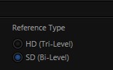
The ‘bi-level’ reference signal long used for standard definition television is often used for genlocking both SD and HD installations.
However, if you are supplying an HD reference signal to TriCaster’s Genlock Input (and your other equipment), select the HD (Tri-level) switch in the Reference Type area of TriCaster’s Genlock settings.
FIGURE 129
Note: Reference Type options do not appear for SD sessions.
![]()
![]()
This setting is applied when a genlock reference signal is not in use. To adjust the setting, supply color bars to an input and pass TriCaster’s video output to a downstream vectorscope. The vectorscope display is completely stable when Center Frequency is properly adjusted.
Note: See also Section 8.2.3, Frame Sync .
![]()
![]()
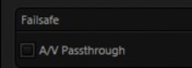
8.1.4 FAILSAFE
TriCaster’s multi-tiered ‘Always on Air’ hardware and software failsafe systems (see Section 2.5.2) provide confidence that short of a complete power failure the show will go on.
In some studio settings, however, more elaborate hardware failsafe systems may be in use. Typically, such systems take over broadcast duties whenever the output signal fails. In such cases, TriCaster’s failsafe video passthrough mechanism (which ensures that video output continues even in catastrophic circumstances) can actually prevent the external system from engaging.
For this reason, a Failsafe section has been added to Output Configuration. Its sole raison d’être is to provide a switch allowing you to disable the A/V passthrough when necessary. By default, A/V passthrough is off.
Hint: Only use fail-safe when a stable video source is connected to video Input 8.