< Previous | Contents | Next >
SECTION 15.7 ADVANCED CONFIGURATION
![]()
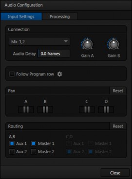
The controls for all inputs (including internal audio sources) as well as the Effects, Stream, Aux 1, 2 and Master 1, 2 output groups include a configuration button located just below the source or output label.
The familiar ‘gear’ icon opens an advanced Audio Configuration panel.
We touched on this panel briefly when we discussed selecting a Connection type for external audio inputs, and (mic) Gain. The Audio Configuration panel offers many more important features and controls, however. Let’s explore these now.
![]()
![]()
Audio and video arriving at TriCaster inputs will maintain sync throughout the system to output or recording.
FIGURE 256
However upstream issues can occasionally cause video to arrive at TriCaster’s inputs later than the corresponding sound.
To mitigate this sort of external problem, TriCaster provides an adjustable Audio Delay setting.
E.g., many cameras support simultaneous digital and analog audio output. In-camera processing can delay digital a/v output, resulting in analog audio output actually leading the digital output by a meaningful measure.
![]()
![]()
Enabling Follow Video options for an audio source directs TriCaster to track switcher operations affecting the related video source.
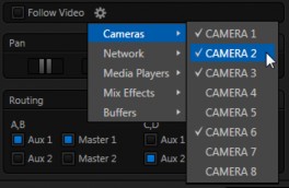
FIGURE 257
Audio for sources with Follow Program video enabled in the Audio Configuration panel is automatically removed from mixed outputs until one or more specified video sources are actually displayed on Program Output.
Hint: When the corresponding video source is not displayed on output, the audio source’s VU meter level is displayed as a grayscale.
![]()
![]()
The Audio Configuration panel also provides complete Pan control.
Pan is a very useful feature. It adjusts placement of sound from source audio channels on the stereo channels
FIGURE 258
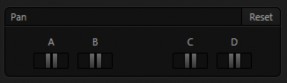
comprising the audio mix(es).
Using Pan, you can place all or part of channel A onto channel B, and vice versa.
When Pan is set to the extreme left position for Input 1a, its audio is sent exclusively to the first channel for the Input 1 group.
Centering the Pan knob labeled A splits the sound received by Input 1a
equally onto channels A and B.
Sliding Pan for Input 1a all the way to the right results in that source only being audible on channel B, removing it completely from its original channel.
Pan also modulates the sound levels on the left and right channels so that the overall volume neither rises nor drops as a result of adjustments.
Hint: “Pan” is not the same as “Balance”. The balance control in a stereo system varies the relative level of the left and right channels, but sound from the left channel will never come out of the right speaker, or vice versa (whereas Pan does permit this to occur).
![]()
![]()
A control group labeled Routing appears below the Pan group in the first tabbed pane (Input Settings) of the Audio Configuration panel for all sources.
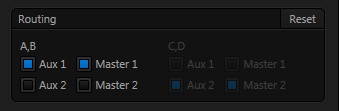
FIGURE 259
The controls in this group determine output routing of the stereo pair(s) comprising the input group. Switches let you send channels A and B to different internal audio buses maintained by TriCaster.
When present, channels C and D can be separately routed. Let’s talk about what an audio bus is and how it is useful before proceeding.
BUSSES AND OUTPUTS
![]()
Consider a very basic audio mixer. Its main audio signal path, from input to output, is properly called the ‘master bus.’ Sound supplied to one or more inputs is placed
on this master bus (in the jargon of audio processing, this is called a ‘send’), which ultimately flows to output connectors.
Slightly more advanced mixers often provide more than one ‘send’ for individual inputs. For example, the sound from all inputs may be sent to the master bus, comprising the ‘master mix’. A different mix, sometimes called a ‘sub-mix’, might also be created by sending certain signals to a secondary (‘auxiliary’, or ‘Aux’) bus.
Hint: A secondary mix, prepared on an Aux bus, can serve many purposes. For example, you might wish to record a mix with all sound from talent microphones but that excludes any sound effects or music.
Let’s summarize what we have learned so far: A ‘send’ pipes audio signals from an input to a discrete pathway called a ‘bus’. Multiple sends can be used to place sound from a given source onto one or more internal busses. OK, what else should we know?
Each audio bus is discrete. Each can be directed along different output paths. And even when the blend of signals it carries is otherwise identical to another bus, it can be processed separately; its level, equalization, and compressor/limiter settings can be unique.
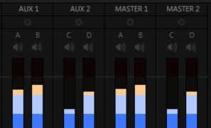
TriCaster provides four primary audio busses. These are identified in the Audio Mixer as:
Master 1
Master 2
AUX 1
AUX 2

Secondary audio busses:
Actually, beyond the primary busses mentioned here, TriCaster maintains a large number of secondary internal busses.
For example, the Solo switch for each input (and output) is actually a ‘send’ that adds sound to a ‘Solo bus’.
Likewise, the IsoCorder™ module (on supporting models) permits discrete recording directly from the unmodified audio input associated with any single video source; really, this constitutes another up to eight additional audio busses.
The Audio Mixer provides control groups for each of these busses (Figure 260), allowing you to set their levels and signal processing.
It is important to understand the distinction between busses and outputs. Now that we understand the former, let’s consider the latter. For TriCaster purposes, an output may be physical, or virtual – i.e., it may involve a connector on the rear panel, or not. For example, the audio recorded by TriCaster does not necessarily require an output connector.
Note: TriCaster Mini’s audio inputs and outputs are stereo. Audio can be routed to the Master 2 and Aux 2 busses, however, for internal use (i.e., sound on these tracks will be captured if you configure an Isocorder recording to include them).
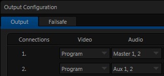
The important thing to realize is that the audio content of any bus may be directed to one or more outputs or, in some cases, to none at all, and – that this is all up to you. By default, the sound from the primary busses is routed to physical outputs as shown in the following table.
Bus | Output Connectors | |||
Analog Outputs | SDI Outputs | AES Outputs | HDMI | |
Master 1 | 1a, 1b (Mini: L, R) | 1 (channels 1 & 2) 3 (channels 1 & 2) | 1a,b (8-input models) | 1 |
Master 2 | 1c, 1d (8-input models) | 1 (channels 3 & 4) 3 (channels 3 & 4) | 1c,d (8-input models) | |
Aux 1 | 2a, 2b (All except Mini) | 2 (channels 1 & 2) | 2 | |
Aux 2 | 2c, 2d (8-input models) | 2 (channels 3 & 4) | ||
However, the standard mapping of busses to outputs can also be modified to suit your specific needs – See Section 8.1, Output Configuration (Figure 261).
SUB-MIXES AND ‘MIX MINUS’
![]()
At times you may require specially configured audio mixes, typically using one of TriCaster’s two stereo Aux audio outputs. For instance – some installations call for sending audio from one or more internal sources (such as a DDR or the Sounds player) to a secondary distribution system.
Alternatively, you may want a ‘clean’ output from one or more sources for use apart from the main primary output mix.
Specialized sub-mixes are often referred to as ‘mix-minus,’ since one or more sources are deliberately subtracted from the main program. Mix-minus capabilities can be invaluable for productions like ‘phone-in’ shows. The remote caller needs to be able to hear the interviewer; but if you simply send the primary mix back to him, he is forced to endure a late-arriving echo of his own voice. Needless to say, this would be confusing and undesirable.
Suppose your interviewer is speaking into a microphone connected to Input 1. The audio from your interviewee is routed into Input 2.
1. For Input 1, enable both the Master 1 and Master 2 switches under Routing in the Audio Configuration panel.
2. For Input 2, enable only Master 1.
This setup gives you a clean output consisting of just the interviewer’s voice on the
Master 1 bus. You can then proceed as follows:
3. Assign Master to Output 1 in Output Configuration (Figure 261).
4. The Master 1 output connectors (1a and 1b) supply your primary audio program output for distribution.
5. Connect TriCaster’s connectors Master 2 *connectors (1c and 1d) to your remote call hookup’s local audio input to send the clean ‘mix minus’ back to your interviewee.
*Note that on certain TriCaster models, Master 2 and Aux 2 signals are only supplied to digital outputs.
This approach eliminates annoying echoing, feedback and the like. Meanwhile, both participants can be heard on the main Program output. Also important, independent control and signal processing is provided for each part of the pipeline.
![]()
![]()
The second tab in Audio Configuration is named Processing, and likewise holds very valuable features.
EQUALIZER
![]()
The seven-band equalizer allows you to ‘shape’ sound to taste, accommodate sources with different acoustic characteristics (say, mismatched mics), minimize feedback or roll off unwanted parts of the audio spectrum.
Enable or disable the Equalizer using the switch beside the label above its control group. The vertical sliders attenuate or boost the tonal range centered on the frequency shown at the top.
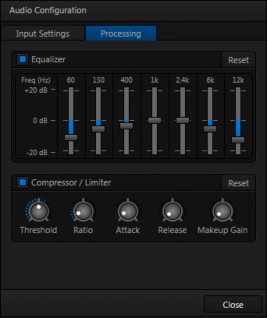
FIGURE 262
The effect applied falls off gradually as sound draws closer to neighboring frequencies on either side.
Click Reset to return all sliders to 0dB.

Compressor … Limiter – what’s the difference, anyway?
Compression and limiting are not really different processes, but rather a matter of degree and perceived effect. Compression, ideally, takes the form of a subtle, almost imperceptible modulation of the sound level to bring it into a more pleasing and convenient range. A limiter is applied more for the purpose of managing, even ‘crushing’, unwanted spikes and transients.
That distinction aside, a limiter is essentially just a compressor set to a high ratio and, generally, a fast attack time. Audio engineers typically consider ‘compression’ with a ratio of 10:1 or more as ‘limiting’.
Hint: Naturally, reducing or increasing the level of one or more tonal bands affects the overall output level as well. This may call for you to trim the main level setting for the affected input or output.
COMPRESSOR LIMITER
![]()
The Compressor/Limiter is capable of preventing clipping (see Section 15.8.1) from unexpected peaks or transients, and making talent sound better than they do in real life, bringing voices, music and other audio sources into an optimal dynamic range.
Being able to do this independently for each output too is icing on the cake, especially for Internet streaming, as it ensures correct levels at any time.
THRESHOLD
Sound above the set Threshold level will be compressed; the amount of compression and the manner in which it is applied are both dictated by the other settings.
RATIO
A Ratio of 4:1 means that if input level is 4 dB over the threshold, the output signal level after compression will be just 1 dB over the threshold. The gain (level) is reduced by 3dB.
Very high ratio settings are the reason for the word “limiter” is part of the title for this feature. The highest ratio setting will effectively reduce any signal that would rise above the threshold all the way down to the threshold level (with the exception of a brief period during a sudden increase in source loudness, as dictated by the Attack setting).
ATTACK
Attack (like Release) is labeled in milliseconds. The setting represents the amount of time it takes for the gain to change by a specified amount.
It would not be grossly incorrect to think of this setting as changing the slope of a graph depicting how aggressively the compressor pursues the target value (defined by applying the Ratio setting to the amount the signal surpasses the Threshold). Shorter values are more aggressive, while longer values are more subtle (and tend to be less noticeable to the audience).
RELEASE
Release is similar to Attack in many ways, but refers instead to the speed with which the compression effect is removed as a source signal falls back on its own so that it no longer exceeds the Threshold.
GAIN
Naturally, compression impacts the overall output level of the source or output. The Gain control allows you to compensate, bringing the post-compressor/limiter signal back to a comfortable nominal range.
Hint: Different circumstances call for different Attack and Release strategies. For example, much less aggressive settings could work nicely for vocals, but fail badly when applied to a snare drum. Many websites provide suggestions on establishing the best compressor/limiter settings for different environments.