< Previous | Contents | Next >
![]()
Having previously connected and configured your audio inputs, let’s explore a few of the standard features in TriCaster’s Audio Mixer.
Hint: You will need to have speakers connected to (at least) the first two connectors (channel 1 and 2) in the Output 1 (upper) row of TriCaster’s Audio Out section (even better, if you have them handy, connect a pair of stereo headphones and put them on).
![]()
![]()
1. Click the DDR 1 tab below the Switcher area of the Live Desktop.
2. Click the + (Add Media) button at lower left in the DDR pane.
3. Click the Practice Session entry under the heading Audio in the Location list at left (this Location entry was created automatically when we imported files back in Section 4.2, Importing Content).
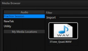
FIGURE 46
4. Find the icon named “3tone_quad.WAV” in the file pane. This is a four channel audio file, with a mid-range tone on channel 1, a higher tone on channel 2, while both channels 3 and 4 both carry a lower tone.
5. Select the icon for this file, and click OK to add this audio file to the playlist.
6. Turn on the Single and Loop switches below the DDR 1 playlist.

7. To avoid any confusion in our little experiment, let’s eliminate all other sounds for now. Click the Audio Mixer tab, and Mute any inputs that show live audio on their respective VU meters by clicking the speaker icons in the titlebar of each control group so they show red background (Figure 47).
8. Make sure audio for DDD 1 player is not muted.
9. Set DDR 1’s Volume sliders to 0dB VU (you can do this quickly by holding down the keyboard Shift key while double-clicking the Volume knobs).
10. Click the DDR 1 tab again, and click the Play button in the DDR 1 pane.
If you have stereo speakers or headphones connected, you should now hear two distinct tones – a mid-range tone from the left, and a higher pitched tone from the right.
11. The VU meter for DDR 1 in the Audio Mixer tab will show matching sound on all four channels.
![]()
![]()
The Audio Mixer’s Pan control is provided in the advanced Audio Configuration
pane.
1. To open this panel, click the Configure button (gear) below the DDR 1 label in the Audio Mixer.
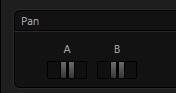
FIGURE 48
A Pan slider is provided for each channel of all audio sources. Sliding a Pan knob left or right actually moves (or ‘pans’) the audio from its original channel onto its neighbor (in the same stereo pair).
2. Mute channels B, C and D for DDR 1.
If the DDR controls are at their default, you will now hear sound only on the left channel.
3. Re-open the Audio Configuration panel.
4. Move the Pan knob for channel A to the extreme right.
Notice that all of the sound previously heard from the left (channel A) is now coming from the right (channel B).
5. Move the slider to the left; as you do, you will hear an increasing amount of sound moving back onto channel A.
Hint: Pan does not have any impact on the levels shown on source VU meters. However you will see its effect on the VU meters for any output mixes the sources are assigned to (in the Routing section of Audio Configuration).
6. At the mid-point (i.e., when the Pan knob for channel A is centered), the audio from the first channel of the file playing in the DDR is divided evenly between channels A and B.
Note: In the center position, Pan controls produce a Mono effect. It’s worth noting that Mic source types (only) are automatically configured with Pan A and B centered, equivalent to a ‘mono’ setting.
7. Move the slider back to the extreme left position. The sound is now entirely sent to channel A, where it was in the first place.
Pan thus provides precise control over where the audio from any channel input is heard – whether exclusively on output channel A, B, or in differing amounts on both channels.
![]()
![]()
Talk is an abbreviation of “Talk Over”. The Talk feature is only shown for inputs when they are set to Mic.
1. Reset Pan and Mute controls to their defaults, and start DDR 1 playing the audio tone file again.
2. Set Input 2 to Mic (using the Connection menu in the Audio Configuration panel for Input 2).
3. Click the Talk button at the bottom of the Input 2 control group, watching DDR 1’s VU meter as you do so.
Enabling Talk causes the level for all other audio sources to drop off by 20dB, allowing Input 1 to dominate. This is very useful for public address announcements, which is its principal purpose.
![]()
![]()
4. Connect (audibly different) audio sources to the input connectors for input 1 and 2 in TriCaster’s Audio In connector group.
5. Open the advanced Audio Configuration panel for Input 1.
6. In the Input Settings tab, enable the Follow Program video switch.
7. Enable Follow Program video for audio Input 2, as well.
8. Select the button for Camera 1 on the Switcher’s Program row.
9. Select the button for Camera 2 on the Switcher’s Preview row.
At this point, you should be hearing audio only from input 1.
Hint: By default, each audio input is configured to follow the video source having the same Switcher row slot, though the Follow switch is disabled. However, it’s valuable to know that these default source relationships can be modified, as we shall see shortly.
10. Click the Switcher’s Take button – keep an eye on the VU meters for Inputs 1
and 2 as you do so.
Notice that when the video source assigned to Camera 1 is selected on the Program (PGM) row, you hear its associated audio input. When you perform a Take the audio source connected to Input 2 in the Audio In section is heard. When Follow is enabled for an audio source, its sound is automatically sent to output whenever video sources it is assigned to follow are displayed on output. In this case, the levels shown in the VU meter for that audio source are drawn in color.
When you switch away from the video source, the VU meter still shows its audio level, but the graph is drawn in grayscale (providing confirmation that audio is present, but indicating that it is not going live to Program out).
Hint: Follow even works when the associated video sources are displayed on output via an M/E or DSK channel.
FOLLOW VIDEO OPTIONS
![]()
The Follow Program video control group for has a drop-down menu that lets you determine exactly which video source, or sources, will be ‘followed’ by the audio source.
Let’s test this:
11. Continue to supply sound to audio Inputs 1 and 2.
12. Use the Follow source menu in the respective Audio Configuration panels to set Input 1 to follow both Cameras 1 and 2, and enable the Follow switch.
13. Configure audio Input 2 identically.
14. Select Camera 1 on the Switcher’s Program row. The audio from both input 1 and 2 should be audible.
15. Switch to Camera 3. The audio from Inputs 1 and 2 is muted on output (and their VU meters will turn gray). If audio Input 3 has sound, you will hear it instead.
16. Switch to Camera 2 and you will hear sound from both Input 1 and Input 2
again.